Quantcast
Channel: Avid CNC
Viewing all 326 articles
Browse latest View live

20 mm Linear Bearing Block + Flush Grease Fitting

$
0
0
20 mm Linear Bearing Block + Flush Grease Fitting

These 20 mm linear bearing blocks are used on our PRO Series CNC machines, for linear travel on both the table and gantry axes. They can be used to replace a damaged or malfunctioning linear bearing block on your machine.The included flush mount grease fitting allows for quick and easy lubrication using our Mini Grease Gun Kit (with optional needle tip adapter).

What's included
  • (1) 20 mm linear bearing block
  • (1) M6 flush mount grease fitting
Plans

Price: $39.75
New in: PRO CNC Accessories

Standard Rack and Pinion Instructions (previous revision)

$
0
0
Standard Rack and Pinion Instructions (previous revision)The R&P has quite a few parts, so we whipped together this quick video on how they all go together. Below that, see our FAQ on the R&P system.

If you would like to purchase this system, it's available in our store here


FAQ on the R&P System
Q: What settings do you use with this system in Mach 3?
A: The base resolution of the system is 190.986 steps per inch with a 200 steps per revolution stepper motor. Multiply this by however many microsteps your driver has. For example, with a G540 (10x microstep), your resolution would be 1909.86 steps per inch.

New in: Archived Instructions

Standard CNC Machine Plans (previous revision)

$
0
0
Standard CNC Machine Plans (previous revision)

CNC Router Parts is pleased to present machine plans for our popular line of affordable, large-format Standard CNC Machine Kits.

The plans shown below feature mechanical components to interface with NEMA 23 motors. For a NEMA 34 system, the Rack and Pinion drives, Z-axis motor mount plate and Z-axis shaft coupler change, but all other aspects of the design remain the same.


Our latest plans (revision are now available in easm format, pdf, and native Solidworks. These plans feature our new drop-in fastener system for easier assembly -- no more fighting with carriage bolts or frustration when things are built out of order. For those not familiar, easm is a free 3D format that allows you to rotate, zoom, and take measurements off of the plans. To view the easm files, just download the free edrawings viewer. Download and enjoy!

Documents
CRP2448
2' x 4' Standard CNC
CRP4848
4' x 4' Standard CNC
CRP4896
4' x 8' Standard CNC
Machine Plans Bundle
(zip Bundle of PDFs/EASMs)
CRP2448-00.zipCRP4848-2012Q2.zipCRP4896-2012Q2.zip
Overall Machine Assembly (PDF)CRP2448-00-01.PDFCRP4848-00-01.PDFCRP4896-00-01.PDF
Base Assembly (PDF)CRP110-00-2448.PDFCRP110-00-4848.PDFCRP110-00-4896.PDF
Gantry Riser Assembly (PDF)CRP120-00-30.PDFCRP120-00.PDFCRP120-00.PDF
Gantry Assembly (PDF)CRP130-00-24.PDFCRP130-00-48.PDFCRP130-00-48.PDF
Z Axis Assembly (PDF)CRP140-00.PDFCRP140-00.PDFCRP140-00.PDF
Solidworks Machine Plans
(zip Solidworks bundle)
CRP2448-SW.zipCRP4848-00sw.zipCRP4896-00sw.zip
For custom sized Standard Series CNC machines, simply choose the instructions for the closest-sized machine above.

For additional help, see our Tips and Tricks for Standard CNC Machine Construction.

New in: Archived Instructions

PRO6060 5' x 5' CNC Router Kit

$
0
0
PRO6060 5' x 5' CNC Router Kit

The PRO6060 CNC machine kit provides a work area large enough for baltic birch or other 5' x 5' sheet goods.

The PRO6060 features Profile Linear Guide Rails, our PRO Rack and Pinion drives on the X and Y axes, and Ballscrew Z Axis, offering higher speeds, greatly improved ease of assembly and machine tuning, and greater stiffness and spindle capacity than our Standard CNC machine kits.

It is designed to easily expand to a larger machine in the future simply by adding more framework, gear rack and linear rail.

Avid CNC PRO4848
PRO6060 5' x 5' CNC Machine Kitbase configuration

Features & Benefits
  • Premium linear motion components (profile linear guide rails, precision ballscrew Z axis, and our PRO rack and pinion drive system)
  • Rigid all-metal design (heavy-duty aluminum extrusion and steel plate construction)
  • Cable management (e-chain) included (standard)
  • Easy Step-by-Step Assembly Instructions
  • Proudly designed and supported in the USA by Avid CNC

Specs
  • Work Area: (PDF)
    • X: 61-3/8" (1559 mm)
    • Y: 61-3/8" (1559 mm)
    • Z: 8" (203 mm) or 12" (304 mm) - minus spoil board thickness [1]
  • Footprint: (PDF)
    • Width: 78-3/4" (2000 mm) or 88-3/4" (2255 mm) with extended gantry [2]
    • Length: 78" (1980 mm)
    • Height:
      • 43-3/8" (1100 mm)
      • 77-1/2" (1970 mm)(with optional Leg Kit)
    • Weight:
      • 332 lbs (151 kg)
      • 403 lbs (183 kg) (with optional Leg Kit)
  • Cutting Speed:
    • 250 IPM+ (NEMA 23 version)*
    • 500 IPM+ (NEMA 34 version)*
  • Cutting Speed:
    • 250 IPM (NEMA 23 version)*
    • 500 IPM (NEMA 34 version)*
  • Rapid Speed:
    • 500 IPM (NEMA 23 version)*
    • 1000 IPM (NEMA 34 version)*
  • Resolution:
    • X/Y: 0.0005” (0.0127 mm)
    • Z: 0.0002” (0.005 mm)
  • Repeatability: +/- 0.002” (0.05 mm)
  • Accuracy: +/- 0.005” (0.127 mm) or better
*Using Avid CNC Electronics

What's included
This kit includes all of the parts needed to build the mechanical portion of a 5' x 5' PRO CNC machine:
  • Aluminum extrusion, cut to length, drilled, counterbored, and tapped for easy assembly
  • Profile Linear Guide Rails, Bearings, and Dust Covers
  • PRO X & Y bumper kits
  • PRO rack and pinion drives and PRO gear rack
  • Ballscrew Z axis
  • All required fasteners
  • Cable Track (E-chain)
In addition, PRO CNC kits are broken down and packed by sub-assembly, helping to make your build straightforward and organized:
  • Machine Base, 5' x 5' (CRP810-00-6060)
  • Machine Risers (CRP820-00)
  • Machine Gantry, 4' (CRP830-00-60)
  • Z-axis (CRP840-00)

Product Notes
  1. We provide separate options for Z-Axis Travel and Gantry Height. Increasing the gantry height will negatively impact machine stiffness. If you plan to cut mostly sheet goods or harder materials, we do not recommend increasing the gantry height. If you require increased Z-Axis Travel, this can be accomplished without raising the gantry with our 12" Ballscrew Z-axis and standard 8" Gantry Height by recessing your work-piece in the table, or off the front of your machine (select the 12" / 8" option below for this configuration).
  2. We offer an extended gantry width option for dual Z-Axis machine configurations. An extended gantry provides the ability to add a second Z-Axis (now or in the future) and maintain access to the full machine work-area for both tools.

Avid CNC PRO4848
PRO6060 5' x 5' CNC Machine Kit
configured with optional Leg Kit (PRO CNC), Plug and Play CNC Control System, and 3 HP Spindle / VFD System.Spoil Board shown can be made from plans in our Design and Make Project Series.

Recommended Accessories

Documentation

Price: $5,175.00
New in: PRO CNC Machines Kits

CNC Tool Tray

Next: Proximity Limit Switch Instructions (previous revision)
Previous: PRO6060 5' x 5' CNC Router Kit
$
0
0
CNC Tool Tray

This project will help you make a custom fit tool tray that organizes your collets, wrenches, and the router bits from our CNC router bit set!  This is a great project for someone looking to gain more confidence with the digital fabrication workflows using our machines with Vectric Aspire or VCarve Pro!


Sources


Using the VCarve Pro Project

We've pre-configured the Vectric project though you can watch the video below to get a better overview of how we made it and what settings to verify before running on your machine. 


New in: Design and Make Project Series

Proximity Limit Switch Instructions (previous revision)

Next: Pepperl + Fuchs Proximity Sensor (NBB7-F10-E0-V1)
Previous: CNC Tool Tray
$
0
0
Proximity Limit Switch Instructions (previous revision)

Thanks for purchasing our inductive Proximity Limit Switch Kit.

The following instructions go over the hardware and software settings required to set up Homing (including auto-squaring of your gantry for dual-drive machines) and Limits with our inductive proximity switches.

The switches themselves are fairly simple, but setting up the coordinated motion of the machine for homing is best done with the following step by step approach.

Step 1: Install Sensors and Verify Motor / Sensor Installation
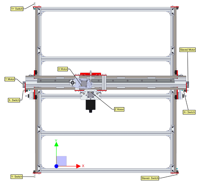
Homing your machine requires moving each axis towards its designated home sensor, so it is important to make sure your motors and sensors are installed in the correct physical positions on the machine.

On machines with slaved axes, it is particularly important to verify which axis is the primary Y, and which is the slaved Y (generally the B axis, however in some cases the A axis, depending on the controller you have), as the Y and slave Y sensors (again, B or A) need to be matched with the correct axis of motion for auto-squaring.

The diagrams below show the correct installation of motors and sensors on the machine:


Note: a single Z switch may also be employed on your system for the purpose of homing the Z axis and serving as a Z+ limit.
To physically install your sensors, install the sensor bodies through the holes in the bumper plates. Each sensor has about an 8mm sensing distance to steel parts, and about 5mm sensing distance to aluminum. We recommend mounting each sensor about 4mm (3/16”) back from the face of the rubber bumper.
Use the jam nuts provided with each sensor to hold the sensor in place, but leave these loose until you complete your homing setup and tune the sensors for squaring.
Step 2: Verify Coordinate System and Motion Direction
Once you have determined your motors and sensors are in the correct positions on the machine, you will want to verify that your machine is moving in the correct direction. To do so, jog the machine by using the arrow keys.

The up and down arrow keys should cause your gantry to move back and forth along the Y axis, the left and right arrow keys should move the Z carriage side to side along gantry (X axis), and the page-up and page-down keys should move the Z axis up and down.

See the diagrams below for the correct machine coordinate system:


It can be helpful to stand at the front of the machine (facing the gantry, looking at the Z axis) in order to visualize the coordinate system. You will want to verify the following:
  • When you press the up arrow key, the gantry should move towards the back of the machine (away from you), and your Y digital readout in Mach should count up (positive direction).
  • When you press the down arrow key, the gantry should move towards the front of the machine (towards you), and your Y digital readout in Mach should count down (negative direction).
  • When you press the left arrow key, the Z carriage should move to your left (towards the Y axis), and your X digital readout in Mach should count down (negative direction).
  • When you press the right arrow key, the Z carriage should move to your right (towards the slaved axis), and your X digital readout in Mach should count up (positive direction).
  • When you press the page-up key, the Z axis should move up (raise away from the table), and your Z digital readout in Mach should count up (positive direction).
  • When you press the page-down key, the Z axis should move down (towards the table), and your Z digital readout in Mach should count down (negative direction).
If any of your axes move in the wrong direction, you will want to switch the “active low” direction pin for those axes under the Config->Ports and Pins->Motor Outputs menu.

Please note, if you change this pin for Y, you will also need to change it for your slaved axis (either B or A)! Otherwise the two sides of the machine will try to move in opposite directions.

For rack and pinion drives, the direction pin setting for the Y and slaved Y motors will be opposite one another, as the R&P drives rotate opposite one another. For Benchtop systems or other dual screw systems, the Y and slaved Y direction bits will be the same.
Step 3: Plug Sensors into Control Unit
Depending on which control system you have, the physical installation of your switches will be different. However, regardless of which controller you have, we recommend setting your switches per the following chart:
Physical SensorPurposeNote
X-X- limit, X HomeSensors X- and X+ will be plugged into the same input port on your controller
X+X+
Y-Y- limit, Y HomeSensors Y- and Y+ will be plugged into the same input port on your controller
Y+Y+ limit
Z+Z+ limit, Z Home
B or AB or A (Y slave) HomeSensor B/A is used for auto-squaring the gantry during homing, so needs its own port on your controller

CRP800 Pre-wired Systems
For our newest pre-wired electronics systems, which feature M12 terminals for the inputs, each sensor has its own port (X+, X-, Y+, Y-, Z, and SLAVED). On these systems, the Y axis is slaved to the B axis, so all setup for the slaved axis (both motor and sensors) should be for "B" in subsequent instructions.

CRP500 Pre-wired Systems
For older pre-wired electronics systems with locking stereo connectors for the inputs, use one of the provided splitter cables to plug the Y+ and Y- sensor cables into the first port (labeled “Y”), and the other to plug the X+ and X- sensor cables into the second port (labeled “X”). The slaved sensor cable will plug directly into the port labeled “A” without a splitter. Note, you must use the provided stereo splitter cable here – mono splitters will not work and may short the 12V power line.

G540
For G540 based systems, see our specific instructions for this control system.

CRP300 NEMA 34 systems
For older PMDX-126 based NEMA 34 systems, you will use the provided 3 pin connectors to install the sensor wires, per the following standard NPN sensor color codes:
  • Black = Signal
  • Brown = V+ (12V)
  • Blue = Ground
  • White = Not Used
These wires can be inserted into the 3 position terminals using a small flat blade screwdriver to actuate the spring-loaded mechanism inside the terminal. A vise or clamp can be help with this.


On the inputs that are shared, the wire ends of two sensors can be wound together and then inserted.


Step 4: Verify Sensor Pin Assignments
Before homing your system, we recommend verifying the pin assignments for all of your sensors. This is best accomplished by using a piece of metal to actuate each sensor while looking at a signal diagnostics screen.

For Ethernet based systems, the screen to use for this is the “ESS Data Monitoring” screen, available from the “Plugin Control” menu, and shown below:

In this screen, you should see a checkmark disappear in one of the input checkboxes when a sensor is actuated. You can place any piece of metal in front of the sensor to actuate it. You should see 3 different signals toggle, one for X sensors, one for Y sensors, and one for the B or A sensor. Take note of the input signals that toggle for each sensor, as these will be used when you assign the signals for homing and limits later. If you have one of our Plug and Play electronics packages and XML files, these pins should be pre-configured for you, but it is worth verifying the signals to make sure they are correct.If you have an older, non-Ethernet system and are using the parallel port for control, you can use the Diagnostics (Alt-7) screen to identify your signals, although the pins are not well labelled. You can use the legend below to identify the pins that are being triggered. The blocks representing the signals will be green, and then will go black when a sensor is triggered. Note, these indicators do NOT work when you are using Ethernet for control, and will all be black in this case, which is why we recommend using the ESS Data Monitoring screen instead.

Step 5: Assign Homing and Limit Pins
Note that if you are using any of our electronics systems or kits along with one of our pre-configured XML files, your homing and limit pins should be configured for you already.

Now that your sensors are installed and the pins associated with them are known, it is time to assign these functions in Mach. Go the Config->Ports and Pins->Input Signals tab. Using the pin numbers you determined in Step 4, above, you will want to enable and assign one pin number for X++, X--, and X Home, another for Y++, Y--, and Y Home, and finally the last pin number for your slaved axis Home, A or B depending on your controller. For each of these signals, you will want to make sure the signals are set to “Active Low”.

Your screen should look like the one above, except you will assign the pin numbers to match those from your testing in Step 4.
Step 6: Set up Homing Routine and Soft Limits
Note that if you are using any of our electronics systems or kits along with one of our pre-configured XML files, your homing routine and soft limits should be configured for you already.

Once you have the hardware and pins assigned correctly, you will want to set your machine up for homing and “Soft Limits”, which restrict motion of the machine to safe locations after homing. To do so, go to the Config-> Homing and Limits screen.
You will want to set this screen up as shown below generally, but with a few modifications based on your machine size:

This screen is set up for a PRO4896 system. For smaller systems, you will want to change the X soft limits.
Step 7: Home the Machine
At this point, you can return to the main running screen in Mach. On systems without a Z sensor, please make sure your Z axis is up and out of the way, as this will not be part of the homing sequence.

When you press the “Ref all Home button”, the machine will home the Z axis first (on systems with a Z sensor), then the Y and Y prime (slave) axes simultaneously, and finally the X axis.

When each side trips the sensor on its respective side, it will stop and back off the sensor. Check the squareness of your machine after homing, and make any necessary adjustments by threading the sensors in and out of their brackets, then re-homing.

Your machine is now homed in “Machine Coordinates”, which can be thought of as the absolute coordinates of the machine. To see what the machine is reading in “Machine Coordinates”, click the “Machine Coord’s” button, which should highlight with a red border. After homing, the X and Y coordinates should read 0, and Z coordinate (on systems equipped with the Z sensor) should read a positive number (depending on your specific configuration).

When you actually start to run G-Code, you will probably want to switch back to “Work Coordinates”, which can be thought of as temporary offsets from the main “Machine Coordinate” system of the machine. To do this, click on “Machine Coord’s” such that the red border disappears. Your G-Code will run relative to this coordinate system. It’s fine if your work coordinates and machine coordinates are the same, and in this case you will be cutting relative to your absolute machine origin. However, in many cases it can be helpful to set up your program somewhere else on the machine, and by editing work coordinates, you can shift where your program will cut on your machine, but the machine will still retain its absolute position.

To enable Soft Limits, which inhibit the machine from moving outside of the limits you have set, you will need to click the “Soft Limits” button such that a green border appears around it.

Troubleshooting Tips
Q)My machine X homes correctly, but when the Y tries to home, it keeps bouncing off the bumper.
A)You may have your Y and slaved Y sensors reversed relative to your motors. Verify your pin assignments match the diagrams shown in Step 1.

Q)My machine is in a limit, and won’t allow me to move!
A)You will need to temporarily override the limits to re-enable motion. This can be done from the “Settings” tab by clicking the manual limit override button. This will allow you to re-enable your machine and drive out of the limit.


Q) My machine is moving away from the home switches during homing instead of towards them.
A) You may have the motors on the wrong side of the machine (see Step 1), or you may have their direction pins configured incorrectly. To change the direction of a motor, see the instructions at the end of Step 2.

New in: Archived Instructions

Pepperl + Fuchs Proximity Sensor (NBB7-F10-E0-V1)

Next: Whiteside Chipbreaker Spiral CNC Router Bit - 1/2" x 1-1/4"
Previous: Proximity Limit Switch Instructions (previous revision)
$
0
0
Pepperl + Fuchs Proximity Sensor (NBB7-F10-E0-V1)

Pepperl + Fuchs NBB7-F10-E0-V1 NPN inductive proximity switch installs easily on any flat mounting surface. These same sensors are included in our Proximity Limit Switch Kits.

These sensors can be used as homing switches or for active safety limits to prevent crashes and protect your machine.

We highly recommend these sensors with our PRO CNC[1] machine kits.

Product Features
  • 7mm detection distance against steel and 4.5mm distance against aluminum. The extended range allows you to completely protect your limit switches with bumpers or other mechanisms and still have sensing range
  • Wide working temperature range (-25 to 70 degrees C), and negligible drift in sensing distance over the working temperature range.
  • Outstanding German quality in component selection and assembly.
  • Each sensor has an LED to quickly indicate function.
Product Notes
  1. Our current PRO Series CNC machines also use the NBN8-12GM50-E0-V1 Pepperl + Fuchs Proximity Sensor. Please refer to our Proximity Limit Switch Kits to find the correct configuration for your machine.

Documentation

Price: $42.00
New in: NEMA 23 CNC Electronics, NEMA 34 CNC Electronics, Proximity Sensors

Whiteside Chipbreaker Spiral CNC Router Bit - 1/2" x 1-1/4"

Next: Whiteside CNC Spoilboard Cutter - 2"
Previous: Pepperl + Fuchs Proximity Sensor (NBB7-F10-E0-V1)
$
0
0
Whiteside Chipbreaker Spiral CNC Router Bit - 1/2

Each flute has small serrations to tear up the chips as the bit is cutting through the project. This bit has a feed rate in-between that of a roughing bit and a standard spiral router bit.

The down cut spiral design provides the best top surface edges, ejecting chips away from the router when routing through material. This design also decreases the tendency to lift thin/small work pieces during CNC routing.


Product Details
Whiteside Chipbreaker Down Cut Spiral CNC Router Bit
  • Solid Carbide
  • Diameter: 1/2"
  • Cut Length: 1-1/4"
  • Shank: 1/2"
  • Overall Length: 3"
  • Flutes: 2

Whiteside Chipbreaker Down Cut Spiral CNC Router Bit - Solid Carbide, 1/2" D, 1-1/4" CL, 1/2" SH, 3" OL, 2 FL


Price: $63.00
New in: CNC Router Bits

Whiteside CNC Spoilboard Cutter - 2"

Next: Grease Gun Needle Tip Adapter
Previous: Whiteside Chipbreaker Spiral CNC Router Bit - 1/2" x 1-1/4"
$
0
0
Whiteside CNC Spoilboard Cutter - 2

Spoilboard cutters are designed specifically to resurface the top surface your spoilboard. They can also be used to plane wood work pieces.Features four wings with carbide tips brazed directly to the tool body.


Product Details
Whiteside Spoilboard Cutter
  • Carbide Tipped
  • Diameter: 2"
  • Cut Length: 1/2"
  • Shank: 1/2"
  • Wings: 4

Whiteside Spoilboard Cutter - Carbide Tipped, 2" D, 1/2" CL, 1/2" SH


Price: $68.00
New in: CNC Router Bits

Grease Gun Needle Tip Adapter

Next: M6 Flush Mount Grease Fitting
Previous: Whiteside CNC Spoilboard Cutter - 2"
$
0
0
Grease Gun Needle Tip Adapter

Grease Gun Needle Tip Adapter, for use with our Mini Grease Gun.


This needle tip adapter allows for easy lubrication of the profile linear bearings used on our current PRO Series and Standard Series CNC machines. [1] It can also be used for lubrication of Benchtop CNC machines.

Grease Gun Needle Tip Adapter

Product Notes
  1. Customers with PRO Series and Standard Series CNC machines purchased prior to 2019 will need to install Flush Mount Grease Fittings on their table and gantry axes to use this needle tip adapter.

Price: $3.95
New in: Other Tooling / Accessories

M6 Flush Mount Grease Fitting

Next: Mini Grease Gun
Previous: Grease Gun Needle Tip Adapter
$
0
0
M6 Flush Mount Grease Fitting

M6 Flush Mount Grease Fittings for use on the table and gantry axes profile linear bearings on our PRO Series and Standard Series CNC machines. These grease fittings allow quick and easy lubrication with our Mini Grease Gun Kit.


For PRO and Standard Series CNC machine customers looking to replace their existing grease fittings, these are available as a pack of 8. This will allow replacement of all table and gantry axes grease fittings. Our Needle Tip Adapter can then be used for periodic lubrication.
Flush Mount Grease Fittings, Pack of 8M6 flush mount grease fittings, pack of 8

Price: $1.95
New in: Other Tooling / Accessories

Mini Grease Gun

Next: Avid CNC Rotary Axis
Previous: M6 Flush Mount Grease Fitting
$
0
0
Mini Grease Gun

Mini Grease Gun, for quick and easy lubrication of profile linear bearings. Available as a complete kit, this grease gun can be used to lubricate any of our CNC machines.


Features:
Mini Grease GunMini Grease Gun with optional Multi-Purpose Lithium Grease and Needle Tip Adapter

Price: $13.95
New in: Other Tooling / Accessories

Avid CNC Rotary Axis

Next: Avid CNC Rotary Axis Assembly Instructions
Previous: Mini Grease Gun
$
0
0
Avid CNC Rotary Axis

The Avid CNC Rotary Axis adds rotary cutting and indexing capabilities to PRO CNC and Benchtop CNC machines.

Features & Benefits
  • Provides both the holding torque required for indexing operations, as well as the speeds sufficient for true rotary milling operations in a production environment.
  • Self-contained within a rigid, all-metal framework to maintain precision alignment between the chuck and tailstock when changing workpieces, regardless of size, even when the entire axis is removed and reinstalled onto your CNC machine.
  • Integrated precision linear rails allow for quick and easy setup for different workpiece sizes, while maintaining the precision alignment of the axis.
  • Software-guided alignment that is fully integrated with our Auto-Z and Corner Finding Touch Plate.
  • Integrated Pepperl + Fuchs inductive proximity sensor provides auto homing and workpiece alignment capabilities.
  • Easy step-by-step assembly and calibration instructions
  • Proudly designed and supported in the USA
Avid CNC Rotary Axis, 1250
Avid CNC Rotary Axis49" (1250mm) frame length

What's Included
  • 4 Jaw self-centering chuck, inside and outside jaws included
  • Planetary gear reducer
  • Adjustable tailstock, live center included
  • Profile Linear Guide Rails and Bearings
  • Low inductance Nema 34 stepper motor and cable (see product options below)
  • Pepperl and Fuchs inductive homing sensor and sensor cable
  • Aluminum frame, cut to length, drilled, counterbored, and tapped for easy assembly
  • All required fasteners and gussets for mounting to your CNC machine (see product options below)

Specs

Mounting Options

The Rotary Axis Kit is designed to be highly versatile and accommodate many different workpiece sizes, while maintaining traditional routing work areas.

It can be mounted to an existing machine parallel with the X or Y axis, or can be recessed into the machine frame to maximize workpiece diameter. Mounting parallel to the Y axis (perpendicular to the machine gantry) maximizes workpiece length, while mounting parallel to the X axis preserves greater traditional routing work area. Recessed mounting can only be achieved parallel to the X axis of the machine.

PRO Series CNC machine mounting options:[2]

  • Table top, parallel or X or Y axis
  • Recessed, parallel to X axis
PRO4848 Rotary Table Top
Avid CNC Rotary Axis, table top mountedPRO4848 machine kit, 49" (1250mm) Avid CNC Rotary Axis, spoilboard, 3 HP Spindle, NEMA 34 Motors
PRO4848 Rotary Recessed
Avid CNC Rotary Axis, recessed mountedPRO4848 machine kit, 49" (1250mm) Avid CNC Rotary Axis, spoilboard, 3 HP Spindle, NEMA 34 Motors

Benchtop PRO and Benchtop Standard mounting options:

  • Table top, parallel to Y axis
BTP2424 Rotary
Avid CNC Rotary Axis, table top mountedBTP2424 machine kit, 39" (1000mm) Avid CNC Rotary Axis, 3 HP Spindle, NEMA 23 Motors

Workpiece Dimensions
Rotary Axis
Frame Length
Maximum Workpiece LengthMinimum PRO Series Machine Width (Recessed Installation)
Mounted Parallel to
Y Axis
Mounted Parallel to
X Axis (Recessed)
Inches (mm)Inches (mm)Inches (mm)Feet
39 (1000)24 (620)N/AN/A
49 (1250)34 (870)28 (736)4
61 (1550)46 (1170)40 (1036)5
72 (1850)57 (1470)52 (1336)6
84 (2150)69 (1770)64 (1636)N/A
112 (2850)97 (2470)91 (2336)n/a

  • Maximum swing over bed: 8" (when mounted directly to aluminum machine frame)
  • Maximum swing over bed recessed: 12"

Size Selection

To determine the optimal rotary axis length for a specific application, start with the workpiece dimensions.

  • Diameter 8" - 12": PRO Series machines only, recessed mounting required. See chart below for recommended rotary axis length.
  • Diameter less than 8": Mounted parallel to X or Y axis on PRO Series machines, or parallel to Y axis on Benchtop machines. To achieve the maximum workpiece diameter of 8" with table top mounting, rotary frame must be installed directly to the machine frame (no spoil board underneath rotary axis). See chart below for recommended rotary axis length.

To gain complete access to the full Y travel of a machine, the rotary axis length must exceed the length of the machine frame (overall footprint will be affected). The chart below shows the required rotary axis length to maintain access to the full Y travel of the machine.

Narrow down the options by selecting the appropriate machine model and size:
Model:
Machine Size:
 

Maximum rotary length for maximum workpiece length
Machine ModelMachine SizeRecessed MountedTable Top Mounted
Rotary Axis Frame LengthRotary Axis Frame LengthTotal Machine Length (with Rotary axis installed)
PRO4824 (4' x 2')49" (1250mm)49" (1250mm)58" (1500mm)
PRO4848 (4' x 4')49" (1250mm)72" (1850mm)82" (2080mm)
PRO4896 (4' x 8')49" (1250mm)112" (2850mm)121" (3070mm)
PRO6060 (5' x 5')61" (1550mm)84" (2150mm)93.5" (2380mm)
PRO60120 (5' x 10')61" (1550mm)N/AN/A
BTP2424 (2' x 2')N/A39" (1000mm)50" (1270mm)
BTP2436 (2' x 3')N/A61" (1550mm)71.5" (1820mm)
BTS2424 (2' x 2')N/A39" (1000mm)52.5" (1330mm)
BTS2436 (2' x 3')N/A61" (1550mm)74" (1880mm)
Product Options

Mounting kits are available for both recessed and table top mounting:

  • Recessed Mounting Kit includes:
    • (2) Undermount bracket with jack screws for easy alignment of rotary frame
    • (2) Mid-support bracket
    • All fasteners required for recessed mounting
  • Table Top Mounting Kit includes:
    • (4) Gusseted corner bracket for mounting to machine frame or spoil board
    • (1) Aluminum joining bar and bracket for fastening headstock to machine frame
    • All fasteners required for table top mounting

Electronics are available for both Plug & Play and DIY control systems:

Product Notes
  1. The Avid CNC Rotary Axis uses a NEMA 34 960 oz-in stepper motor. A motor adapter cable will be provided to allow compatibility with NEMA 23 control systems. If your control system does not contain a 5th motor driver, please Contact Us for upgrade options. If you are purchasing one of our Plug and Play CNC Control Systems, select the "5th drive upgrade" option.
  2. When ordering a new PRO Series CNC Machine it is recommended to budget 2' of Y travel or 1' of X travel, in addition to your desired traditional routing work area for a permanently installed rotary axis. For example:
    • 4' x 4' traditional work area with rotary axis mounted parallel to the X axis, a 4' x 6' machine is required
    • 4' x 4' traditional work area with rotary axis mounted parallel to the Y axis, a 5' x 4' machine is required

Documentation

Price: $2,470.00
New in: Avid CNC Rotary Axis

Avid CNC Rotary Axis Assembly Instructions

Next: CNC Router Parts is becoming Avid CNC
Previous: Avid CNC Rotary Axis

CNC Router Parts is becoming Avid CNC

Next: CNC Software Setup Guide [Mach3]
Previous: Avid CNC Rotary Axis Assembly Instructions
$
0
0
CNC Software Setup Guide [Mach3]

Thursday, May 16, 2019

We’re excited to announce that CNC Router Parts is becoming Avid CNC!

For the past 11 years, we’ve been passionate about our mission to provide professional machine tools at an exceptional value that are accessible to everyone.

Avid CNC is a new name that represents the excitement and enthusiasm that we bring to this mission every day.

Avid CNC

Simply put, we’re avid about CNC, and we think our name should reflect that.

Our team, leadership, mission, and commitment to our customers will all remain the same, just with a new name as we continue forward with exciting products and innovation.

Thank you to our customers, partners, and supporters, from the entire team at CNC Router Parts / Avid CNC!


CNC Software Setup Guide [Mach3]

Next: PRO CNC Plasma Instructions [Mach3]
Previous: CNC Router Parts is becoming Avid CNC
$
0
0
CNC Software Setup Guide [Mach3]
Please Note
These instructions are applicable for Mach3, our previous CNC control software.

The current version of these instructions for Mach4 are available here:
CNC Software Setup Guide.


This guide provides step by step setup instructions for configuring the Ethernet Smoothstepper (or ESS) for use with your CNC Router Parts Electronics and Mach3.

The Ethernet Smoothstepper manual, along with other additional documentation, can be found on the Warp9 website (the manufacturer of Smoothstepper).

Please Note
The companion video to this guide (above) is out of date and includes steps for installing the Ethernet Smoothstepper plugin and our Auto Z Touch Plate script. These steps are now performed automatically for you by our latest Mach3 installer. This video guide remains a very useful walkthrough of the setup process otherwise, however those steps may now be ignored.If you have purchased one of our Plug and Play Electronics Systems, your Ethernet Smoothstepper is already fully-installed and ready to go, and you should proceed with the steps below to configure your PC with Mach3.

For help with the physical installation and configuration of the Ethernet SmoothStepper, please first refer to the Ethernet Smoothstepper Hardware Installation Guide and then return to these instructions when you are ready to proceed.

1. Install Mach3
First, download and install the trial version of Mach3. [download Mach3 installer]

Please install Mach3 to its default location (C:\Mach3). Do not install the parallel port driver if asked during the installation process.

Mach3 will run in Demo mode until "unlocked" with the purchased license file, however you may continue with the remaining setup steps in this guide while running Demo mode if you wish.

If you purchased Mach3 from CNC Router Parts, you will receive your license file along with detailed instructions for installing it via email.

2.Install the Pre-Configured XML File for your system
Download and install the appropriate Pre-Configured XML File for your electronics to your C:\Mach3 folder (do not run Mach3 yet).

3.Plug in Ethernet Cable
Your Ethernet cable should now be plugged in to both your PC and the Ethernet Smoothstepper.

4.Configuring your PC Settings
The Ethernet Smoothstepper SCU (System Configuration Utility) is the quickest and easiest method to perform the basic configuration step to connect your computer with your Smoothstepper and CNC electronics. Simply visit the SCU (System Configuration Utility) page, and follow the instructions there to download and run this utility.

5.Additional PC Configuration
The Ethernet SmoothStepper solves or greatly reduces most potential Windows-related communication issues by providing a dedicated real-time DSP (digital signal processor) to handle the precise timing of step and direction signals to your CNC electronics.

Following these additional Windows configuration steps will help to create the most stable environment for Mach3 and further reduce the opportunity for other processes to create delays or otherwise interfere with smooth and uninterrupted communication from Mach3 to the SmoothStepper:
  1. On the ethernet adaptor interface (now named “SmoothStepper Network XX”), disable all protocols except Internet Protocol Version 4 (TCP/IP v4)
  2. In the ethernet adapter properties, under the “Advanced” tab, disable the “Energy Efficient Ethernet” and “Green Ethernet” properties (Note: either or both of these properties may not exist).
  3. In the ethernet adapter properties, under the “Power Management” tab, uncheck “Allow the computer to turn off this device to save power” option (Note: the Power Management tab may not exist, in which case skip this step).
  4. Turn off/disable the Windows screensaver.
  5. Configure Power Management - create a new power plan called “CNC”, starting with the “High Performance” as the template, and set everything to “Never” for both the “Plugged In” and “On Battery” settings (Dim Display, Turn off Display, Put Computer to Sleep).
  • NOTE: You must go into the “Change advanced power settings” to configure the Hard Disk to never turn off (on battery or plugged in).
  • Disable (preferably uninstall) any third-party virus scanning/protection software.
  • Configure Windows Defender (Windows 8 ) / Windows Security Essentials (Windows 7) to never run a scheduled scan (note: this is not possible on Windows 10).
  • Configure Automatic Updates:
    • If you are running Windows XP, Vista, 7, or 8, disable automatic updates altogether.
    • If you are running Windows 10:
      • under Advanced Options, set the “Choose how updates are installed” setting to “Notify to schedule restart”
      • check the “Defer Updated” checkbox (if present)
  • Create a shortcut to run Mach3 with “Above Normal” priority.
    • You can download one here: Mach3 Loader (Priority) Shortcut (save it to your desktop), or create a new shortcut on your desktop manually and edit the following settings:
      • Target: C:\Windows\System32\cmd.exe /c start "Mach3" /AboveNormal "Mach3.exe"
      • Start In: C:\Mach3
      • Optionally, set the shortcut icon by navigating to "C:\Mach3\Mach3.exe" and selecting the Mach3 icon.
    • Drag the new shortcut to the task bar to pin it there for convenience.

    6. Mach3 Configuration.
    Note: if you are using one of our Pre-Configured XML Files, the following setting should already be present.
    • In Mach3, under “Config”->”General Config, set the “LookAhead” setting to 100 (the default is 20).
    • In Mach3, under “PlugIn Control”->”Main Config”:
      • set the Controller Frequency to 1kHz
      • set the “Watchdog” timeout to 3.1 seconds
      • Under “Noise Filtering of Inputs”, set:
        • Probe: 0.00
        • Estop: 200.00
        • Jog: 0.00
        • Limit: 200.00
        • Home: 0.00

    7.Best Practices for CNC Operation.
    • Always turn-off or disable all other network connections (i.e. Wifi) when running a CNC program in Mach3.
    • Check Windows Task Manager for other processes taking up significant CPU or Memory resources.


    If you have additional questions or run into issues with your setup, feel free to Contact Us and we will be happy to assist you.


    New in: Archived Instructions

    PRO CNC Plasma Instructions [Mach3]

    Next: Auto Z and Corner Finding Touch Plate Instructions [Mach3]
    Previous: CNC Software Setup Guide [Mach3]
    $
    0
    0
    PRO CNC Plasma Instructions [Mach3]

    Please Note
    If you are using Mach4 CNC Control software with your PRO CNC Plasma system, refer to the current Mach4 PRO CNC Plasma Instructions.
    Our PRO CNC Plasma systems are currently compatible with Hypertherm 45XP, 65, 85, and 45 (discontinued) systems. These torches are available from a number of sources, although we recommend Baker's Gas if you are ready to purchase. To work with our torch mount, Ohmic touch-off and torch height control system, the Machine Torch, and CPC options are required. Shielded (Mechanized) Consumables are required for use with machine torch systems.

    In order to work with the Ohmic touch-off feature that comes standard with our torch mounts, an ohmic retaining cap (sold separately) is required. Below are links to compatible configurations of Hypertherm torches and retaining caps.

    Recommended Torches and Retaining Caps:
    Plasma Setup
    The following steps and downloads are required to set up plasma on your machine:
    1. Follow the instructions in our Getting Started Guide for mechanical setup and wiring of the plasma components.
    2. Follow the instructions in our Plasma Software Setup and Usage Guide to install and configure Mach3 for plasma. This manual is also a helpful reference for plasma-specific software features like torch height control and anti-dive
    3. Follow the instructions in our Plasma Retrofit Guide to install your Torch Height Control card (not necessary if purchased with CNC Router Parts electronics) and update Mach 3 settings for plasma.
    4. Install the Post processor for SheetCAM, which adds a material touch-off of material to the beginning of each pierce. The link contains both an Ohmic touch off post (recommended for most applications), or a Mechanical touch off post using the floating head switch (recommended only for special applications like rusty materials)
    5. Go through our Operation Checklist before cutting on the machine to insure successful operation.
    6. For advanced troubleshooting of torch height control and anti-dive settings, the THCLogAnalyser application can provide helpful information and visualization of log data.

    New in: Archived Instructions

    Auto Z and Corner Finding Touch Plate Instructions [Mach3]

    Next: CNC Software Setup Guide
    Previous: PRO CNC Plasma Instructions [Mach3]
    $
    0
    0
    Auto Z and Corner Finding Touch Plate Instructions [Mach3]

    The Avid CNC Auto Z and Corner Finding Touch Plate system allows for quick and precise setting of your tool height and work piece corner/edge location.


    Please Note
    If you are using Mach4 CNC controller software, refer to our Mach4 Auto Z and Corner Finding Touch Plate Instructions.If you purchased one of our Plug and Play CNC Control Systems, Steps 2-4 below are automatically performed for you when you use our latest Mach3 installer and XML configuration files (version 19.2 or later). Please refer to the Mach3 CNC Software Setup Guide for more information.
    Using the Auto Z and Corner Finding Touch Plate with Mach3
    Setup of the Auto Z and Corner Finding Touch Plate is fairly straightforward:
    1. Plug the unit in.
      1. For our CRP800 Plug and Play CNC Control Systems (both NEMA 23 and NEMA 34), just plug the M12 connector from your touch plate into the appropriate input for configuration file your are using:
        1. For our revision 19.2 configuration files, use the "AUX 2" sensor input (Port# 2, Pin# 8)
        2. For our revision 16.1 - 18.3 XML configuration files, use the "AUX 1" sensor input (Port# 2, Pin# 9)
        3. For earlier revisions of our XML configuration files, use the "Z" sensor input (Port# 2, Pin# 6)
        4. In either case, you can use a different AUX port if you prefer, although you will then need to re-assign the pin used for the "Probe" function.
      2. For older PMDX-126 based NEMA 34 systems, just connect the two leads on the unit to “Signal” and “Ground” on one of the 3 pin connectors supplied with your panel, and plug into the red input signal board. NOTE, the "Ground" should be the lead connected to the magnet (or clip on older models), while the "Signal" should be the lead going to the brass puck on the touch plate.
      3. For a DIY system based on the PMDX-126 breakout board, just connect the two leads to an input pin and a common on J11.
      4. For a G540 based system, you will need to wire one of the leads to an available input (pins 1 through 4 on the G540), and the other lead to the G540 power supply common (V-, on pin 12 of the G540). NOTE, the V- connection should be the lead connected to the magnet (or clip on older models), while the input pin should be the lead going to the brass puck on the touch plate.
    2. Set up the input pin for the “probe”.
      You will need to configure the probe as an active low input on an available open input. The example below shows pin 15 being used, but if you are already using pin 15 for something else (such as a limit switch or estop), you will need to use another available input.

      If you have a CRP800 Plug and Play CNC Control Systems, the probe input should already be set up on Port# 2, Pin# 9 (tied to the "AUX 1" input on your controller), or Pin#6 (in older revisions of our configuration files, tied to the "Z" input on your controller).

      Any changes to pins are made from the Config->Ports and Pins->Input Signals tab.
      Plate Ports and Pins Input Signals
    3. Test the input to insure proper function and pin assignment.
      If you have an Ethernet Smoothstepper (pre-installed in most plug and play packages), go to the diagnostics page under Plugin Control->ESS Data Monitoring. From this menu, you should be able to see an input signal toggle (check mark turn on and off) when you touch the magnet (or clip on older models) to the brass puck of the touch plate. If you do not see the same signal toggling that you assigned to the probe input, you should go back and re-assign the signal. If you do not see a signal toggling at all, contact us before proceeding further.
      Input Signal Diagnostics
    4. Add the Visual Basic code to the “Auto Tool Zero” button
      1. Go to the Operator menu and select “Edit Button Script”; the configurable buttons on the page will start flashing.
      2. Click on the “Auto Tool Zero” button; this will bring up a window with code you can edit.
        Auto Z and Corner Finding Touch Plate Script Editor
      3. Copy the code below into the editor (replacing any existing code):
        If your CNC control computer is not connected to the internet, you can also download this script to transfer it manually. Once the script is on your control PC, simply open with Notepad and then copy/paste into the editor.
      4. Save the file and exit the editor, and then restart Mach3.
      5. If your machine has an aluminum table top, make sure there is something non-conductive between the z touch assembly and the table top to avoid creating a false signal. Before running the routine for the first time, make sure the emergency stop is accessible in case something is set up incorrectly to avoid over-driving your z axis.

    New in: Archived Instructions

    CNC Software Setup Guide

    Next: 8.7 HP Spindle Tramming Mount
    Previous: Auto Z and Corner Finding Touch Plate Instructions [Mach3]

    8.7 HP Spindle Tramming Mount

    Next: ER32 Collet and Nut Set, Imperial
    Previous: CNC Software Setup Guide
    $
    0
    0
    8.7 HP Spindle Tramming Mount

    Our 8.7 HP Spindle Mount is machined from solid blocks of billet aluminum for unparalleled strength and rigidity. It is designed with integrated auto-tramming for easy mounting, adjusting, and squaring for our 8.7 HP Plug and Play Spindle / VFD System or other similar cutting tool.

    It can mount directly to 15 series, 40mm series aluminum extrusion, or to the Ballscrew Z Axis on our PRO CNC and Benchtop PRO machines.


    8.7 HP Spindle Tramming Mount from Avid CNC

    8.7 HP Spindle Tramming Mount w/ included hardware


    8.7 HP Spindle Tramming Mount from Avid CNC

    Assembled 8.7 HP Spindle Tramming Mount

    Plans - Base Adapter

    Plans - Tramming Plate

    Price: $125.00
    New in: Router and Spindle Mounts, CNC Spindle / VFD
    Viewing all 326 articles
    Browse latest View live


    <script src="https://jsc.adskeeper.com/r/s/rssing.com.1596347.js" async> </script>